Δευτέρα 26 Σεπτεμβρίου 2011

MEADE ETX-70AT TELESCOPE REMOTE PC AND ARDUINO CONTROL

These fine nights of September when Orion rises early the morning above the horizon, and Jupiter dominates the sky, its a pleasure to use the small ETX-70 telescope guided by its Autostar 494 controller. That telescope costed a mere 200 Euros at Lidl and in my opinion it isn't just a fine little telescope for the beginer, but it's also  perfect for land surveing. When Lidl sold its Bresser microscope (another 60 Euros welll spend), it supplied it with a USB camera that fits not only to the microscope , but via an (supplied) adapter to the 1.25'  eyepiece holder of the ETX-70. Even though the USB video adapter has a resolution of just  640 x 480 pixel , it is very good for land surveying as  shown on the following  video. At this case the distance to the subject (the Mi-8 Helicopter) was about 2.5 kilometers, temperature was about 27 deg. C, a sea area existed between the scope and the target and atmospheric conditions far from perfect. Barlows 3x lens was also used that deteriorated the resolution but I wanted to push it to its limits.


From the point of view of an electronics engineer the most interesting feature of the ETX-90  , is the precise guiding mechanism which can be controled by the computer's serial port. All you need is the optional 506 cable set from Meade which is actually an RS232 to I2C adapter that connects to the AUX port of the microscope. A lot of info is written about Meade's serial protocol but the best way to learn about it (exactly as I did) is to tap the serial cable and spy on the data when controlling the telescope with a proper software such as Drsoft 's Meade control panel , Carte des Ciels or Stellarium. A much more elegant solution to taping the cable is to duplicate the controling serial port using a serial to ip server, and open a teminal (like TeraTerm) at 9600N81 to view and log the traffic.After all my finds were :

#:Mn#  Slew north (up)
#:Ms#  Slew south (down)
#:Me#  Slew east  (left)
#:Mw#  Slew west  (right)

#:Mw##:Mn#  Slew right up    (NW)
#:Mw##:Ms#  Slew right down  (SW)
#:Me##:Mn#   Slew left  up    (NE)
#:Me##:Ms#   Slew left down   (SE)

#:Qn##:Qs##:Qe##:Qw# Stop movement after above commands
#:Q# Stop movement for all motors

#:Sw2#   Slew speed slow
#:Sw3#   Slew speed medium
#:Sw4#   Slew speed fast

FOCUS  CONTROL - there isn't any focuser on the scope - we will talk about it later.
#:F+#    Focus +
#:F-#   Focus -
#:FQ#   Focus Stop
#:FF#   Fast Focus
#:FS#   Slow Focus
 
After reading the excellent info on http://www.weasner.com   I learn that : " when typing a single control-F on the terminal  the Autostar should echo an "A" or "P" depending upon whether it's
 set up as Alt/Az or Polar mount status and when typing #:GVF#  it should respond with its identification string, including the word Autostar and a time and date (when that firmware version
 was built at Meade) ".
Indeed  :
 Ctrl -F    ---> A
#:GVF#   ---> #Autostar|A|12Ea #    
Σάββατο 10 Σεπτεμβρίου 2011

RECHARGEABLE BATTERY QUALITY MONITOR

       Using micro-controllers one can easily (!!!) make an intelligent rechargeable battery monitor in order to check if his NiMh or Nicads are in good condition. Let's take my favorite Arduino for example. It has 6 analog ports, so we can take a six battery holder, cut all inter-cell connections (they are connected in series), put a resistor in series with each cell (it we are keeping it simple - a current source would be much better) and measure and log the voltage as it drops through the resistor. We could also program some kind of Processing script to display the results graphically on the computer.
       Well, I used a different - and  faster approach. I used my intelligent 10-cell charger and my Sony TRV-22 DVR in photo mode and its simple intervalometer. TRV-22 can take photographs every 1, 5 or 10 minutes in memory stick (120 photos 640x480 resolution on 8MB memory stick)  I fully charged the batteries and then discharged them , photographing the charger's leds every 10 minutes. When a cell is being discharged a red led flashes slowly  and when discharging is over it lights steadily until full charge when it  finally becomes green. The fist discharged battery is the weakest and the last one has the maximum amount of energy. In the following time- lapse video you can see that batteries 8 and 9 are the first to begin charging (that means that are the first to discharge - the ones with the less energy) because their leds lite steadily first of all the others. Battery number 3 is the best because its charging begun 2h 45' after no's 8 and 9 (by examining the EXIF metadata in every pictures file).
      Night vision is enabled on TRV-22 because most of the process took place at night. Here is a video of the discharging sequence :  


The above procedure can also be accomplished with a web cam and a capture program with intervalometer function. There are a few free ones on the web. Timing error if 10 minute interval is used is +/- 10min. Following time lapse video shows charging sequence :


Δευτέρα 5 Σεπτεμβρίου 2011

DRAGON BOAT

Dragon boat is a wooden speed boat model made in Japan at late 50's.  Japan's  economy was trying to recover from WWII  and toy companies (like Ito) used Japanese households to assemble their products  like this one. My grandfather who was a sailor gave  it as a present to his son (my late uncle) and my first thought was to use it to tow the depth sounder platform in order to accomplish some lake topography and bathymetry missions. Later I discovered (the hard way ) that these thoughts were disastrous for the boat model and potentially dangerous for me.
The Dragon that gave the name to this model was once painted on both sides of the boat. Unfortunately it was so worn-out that I had to wipe it out completely.
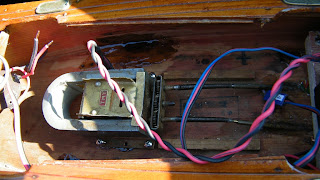
Anyway,  I made an ESC with a picaxe and two mosfets and I used a standard servo for steering. The 35MHZ receiver antenna is visible on the following images


Here is a rather shaky  video. I'm sorry for this  but it 's quite difficult to take video and pilot  the model simultaneously.


INFRARED REMOTE CONTROL CODE HACKING FOR AUDIO - VIDEO DEVICES

Remote controlling audio-video devices like cameras, DVR's , VCR's is one of my favorites.
Imagine remote controlled  pan - tilt cameras for wildlife photography, target acquisition etc !!

SONY DVR TRV22E-TRV11E infrared remote control hack

At first a pulse of 2.4ms (of 38khz)  must be send followed by a 600us pause
"1" (38KHZ ) duration is 1200us, "0" (38KHZ)  is 600us and inter-digit (pause) duration is 600us.
After last bit we have a pause of 19.5ms.  Each pulse train  must be send 3 times.


{1,0,0,1,1,0,0,1,0,0,1,1,1,0,1}   Start-Stop Recording
{1,0,1,0,1,0,0,1,0,0,1,1,1,0,1}   Snap Shot
{0,1,0,1,1,0,0,1,0,0,1,1,0,1,1}   Zoom In
{1,1,0,1,1,0,0,1,0,0,1,1,0,1,1}   Zoom Out


JVC GRD-240E DV camera infrared remote control hack

At first a pulse train  of 8,8ms (of 38khz)  must be send followed by a 4ms pause
"1" (pause ) duration is 1500us, "0" (pause)  is 600us and signal (38KHZ) duration is 600us.
After last bit we have a pause of 17.5ms. Each pulse train  must be send once.

{1,1,0,0,1,0,1,1,1,0,0,1,1,0,1,0}   Start-Stop Recording
{1,1,0,0,1,0,1,1,1,1,1,0,0,1,1,0}   Power Toggle
{1,1,0,0,1,0,1,1,1,0,1,1,1,0,1,0}   Snap Shot 
{1,1,0,0,1,0,1,1,0,1,0,0,1,0,1,0}   Zoom In
{1,1,0,0,1,0,1,1,1,0,0,0,1,0,1,0}   Zoom Out

Fujifilm Finepix S2000hd infrared remote control hack
At first a pulse of 9,2ms (of 38khz)  must be send followed by a 4.48ms pause
"1" (pause ) duration is 1620us, "0" (pause)  is 600us and signal (38KHZ) duration is 580us.
After last bit we have a pause of 40.6ms. Each pulse train  must be send once.


 {1,1,0,1,0,0,1,1,0,0,0,0,1,1,0,0,0,1,0,0,0,0,0,1,1,0,1,1,1,1,1,0}  PHOTOS |>
{1,1,0,1,0,0,1,1,0,0,0,0,1,1,0,0,1,1,1,0,0,0,0,1,0,0,0,1,1,1,1,0}  MENU / OK
{1,1,0,1,0,0,1,1,0,0,0,0,1,1,0,0,1,0,0,1,0,0,0,1,0,1,1,0,1,1,1,0}  FUNCTION
{1,1,0,1,0,0,1,1,0,0,0,0,1,1,0,0,0,0,0,1,0,0,0,1,1,1,1,0,1,1,1,0}  DISP / BACK
{1,1,0,1,0,0,1,1,0,0,0,0,1,1,0,0,1,0,1,0,0,0,0,1,0,1,0,1,1,1,1,0}  Right Arrow
{1,1,0,1,0,0,1,1,0,0,0,0,1,1,0,0,0,1,1,0,0,0,0,1,1,0,0,1,1,1,1,0}  Left Arrow
{1,1,0,1,0,0,1,1,0,0,0,0,1,1,0,0,1,1,0,0,0,0,0,1,0,0,1,1,1,1,1,0}  Up Arrow
{1,1,0,1,0,0,1,1,0,0,0,0,1,1,0,0,0,0,1,0,0,0,0,1,1,1,0,1,1,1,1,0}  Down Arrow
{1,1,0,1,0,0,1,1,0,0,0,0,1,1,0,0,1,1,0,1,0,0,0,1,0,0,1,0,1,1,1,0}  hex 2 Zoom In
{1,1,0,1,0,0,1,1,0,0,0,0,1,1,0,0,0,1,0,1,0,0,0,1,1,0,1,0,1,1,1,0}  hex b Zoom Out

Important !! Last two commands are not implemented at the official Fujifilm remote control.


INFRARED REMOTE CONTROL CODE HACKING FOR HVAC DEVICES

In a modern house , most electronic devices are controlled by an infrared remote. Hacking the infrared codes gives you endless possibilities:  Using a micro controller you can built an universal HVAC controller which can map the desired indoor temperatures and control all devices like air conditioning units, ceiling fans , heaters etc. You can use input from:
  • outdoor/indoor  humidity temperature and solar radiation sensors
  • input and return water temperatures from heater 
  • solar collector and/or electric boiler temperatures
  • time of day - season rtc
  • solar radiation sensors
  • movement sensors (to control temp of an occupied room)
  • internet weather forecast data
  • rain sensors
to control
  • oil boiler set point
  • air conditioning unit temperature and/or functions  (eg dehydrating)
  • ceiling fan speed to equalize  temperature in a room 
  • fan coil fan speed control
To be more specific you can control oil boiler set point by using a common servomotor connected mechanically to the water temperature knob,  infrared diodes to transmit commands to airconditioning units and ceiling  fans. I personally use three one-wire (or LM35DZ) sensors (one at the floor level, one at 1m height (bed level)  and one at 2.8m (ceiling level) to control ceiling fan speed  in conjunction with all other HVAC devices to maintain a steady comfort temperature and to not waste energy by over heating ceiling in winter or over freezing floor in summer. Using movement sensors the system knows when a person is in the room and acts accordingly - even at night when the person is sleeping.

Below are some hacked infrared codes from my HVAC devices:

HITACHI Inverter Air conditioning

At first a pulse of 9,2ms (of 38khz)  must be send followed by a 4.48ms pause
"1" (pause ) duration is 1620us, "0" (pause)  is 600us and signal (38KHZ) duration is 580us.
After last bit we have a pause of 40.6ms. Each pulsetrain  must be send once.
All pulses must be send. I have to separate them in command and common parts in order to use a micro controller for temperature control.

Power on (All Auto -mode auto, fan speed auto, set temp auto)
{1,0,0,0,0,0,0,0,0,0,0,0,1,0,0,0,0,0,0,0,0,0,0,0,0,0,0,0,0,0,1,0,1,1,1,1,1,1,0,1,1,1,1,1,1,1,1,1,0,0,0,0,0,0,0,0,0,0,1,1,0,0,1,1,1,1,0,0,1,1,0,0} 
{0,1,0,0,1,0,0,1,1,0,1,1,0,1,1,0,1,1,0,0,1,0,0,0,0,0,1,1,0,1,1,1,0,0,1,0,0,0,0,0,1,1,0,1}  {1,1,1,1,0,0,0,0,0,0,0,0,1,1,1,1,1,1,1,1,0,0,0,0,0,0,0,0,1,1,1,1,1,1,1,1,0,0,0,0,0,0,0,0,1,1,1,1,1,1,1,1,0,0,0,0,0,0,0,0,1,1,1,1,1,1,1,1,0,0,0,0,0,0,0,0,1,1,1,1,1,1,1,1,1,1,1,0} {1,0,1,0,0,0,0,1,0,1,0,1,1,0,0,0,1,1,1,1,0,1,1,1,0,0,0,0}
{0,0,0,0,0,0,0,0,1,1,1,1,1,1,1,1,0,0,0,0,0,0,0,0,1,1,1,1,1,1,1,1,0,0,0,0,0,0,0,0,1,1,1,1,1,1,1,1,1,1,0,0,0,0,0,0,0,0,1,1,1,1,1,1,1}

Power off :Repeat all the above and  change red sequence with this:
{1,0,1,0,0,0,0,1,0,1,0,1,1,0,0,0,0,1,1,1,0,1,1,1,1,0,0,0}

Westinghouse ceiling fan infrared control hack (UC7130T)
 
We have no header or "wake-up" pulse here. Logic "0" is a pause of 840us followed by a pulse of 420us of 38KHZ and logic "1" is a pause of 430us  followed by a pulse of 820us of 38KHZ. After last bit we must wait for 15ms to send same sequence again. Each sequence  must be send at least 3 times. Infrared sender must have a powerful output (multiple leds and/or high voltage (9V) on collector - darlington driver).

{0,1,0,0,0,0,0,0,0,0,0,1,0}   FAN OFF
{0,1,0,0,0,0,0,0,0,1,0,0,0}   FAN SPEED 1 (MIN)
{0,1,0,0,0,0,0,0,1,0,0,0,0}   FAN SPEED 2 (MED)
{0,1,0,0,0,0,0,1,0,0,0,0,0}   FAN SPEED 3 (MAX)
{0,1,0,0,0,0,0,0,0,0,0,0,1}   LIGHT ON/OFF
{0,1,0,0,0,0,0,0,0,0,1,0,0}   LIGHT SLEEP


INSURGENT DETECTION - MONITORING AUV

This post has no comments


AUTONOMOUS - REMOTE CONTROLLED VEHICLE

It s a simple implementation of ardupilot ver 1.0 with a few add-ons. FTDI usb to serial interface is used to program the ardupilot, an RF data link at 9600baud transmitts positioning and other data , and standard 35 MHZ r/c equipment is used for vehicle control and activation of autopilot. Oziexplorer is used as the logging and  mapping interface (for real time position indication) via  a simple trick : Distance to home (to launch point) is injected into GGA  NMEA  sequence instead of altiude (by regenerating the sequence and transmitting it via rf )
Unfortunately due to the complete lack of suspension  and because of the ultra simple steering mechanism of the extremely cheap (6 euro's ) jeep model, when  RTL (Return To Launch) function was implemented, it  produced a funny track to home as shown in the last capture from Ozi interface.


The implementation of RTL function


AUTONOMOUS / REMOTE CONTROLLED WATER RESERVOIR SURVEY


Another implementation of arduino micro-controller auto pilot is the lake surveying  ROV . The main advantage of such an implementation is that ,the greatest percentage of lake area has depths less than 1/2 meter and so it's quite impossible to measure it using conventional depth sounding techniques.
A motorized (via a Graupner outboard motor) plywood platform on 2 cylindrical  floats (catamaran style),  with just 5 cm drought fits the task ,  with plenty of electronics on board such as:
  • A picaxe ESC (electronic speed control)
  • A standard 4 channel r/c receiver at 35 MHZ
  • An Arduino board with Em406 GPS 
  • An intelligent depth sounder (with rs232 output)
  • A 433MHZ 9600 baud telemetry transmitter  or an XBee pro link at 900MHZ.
      and for the monitoring station:
  • A laptop that runs Winxp and Oziexplorer (my favorite mapping program)
  • An underwater  camera with video link (for clearing underwater obstructions) 
  • A laptop for data logging - real time position indication -video capture


Surveying ROV with Gps , Autopilot, RF data link and depth sounder

Quite a big team is required for such a project. You may need :

  • a 4x4 truck
  • a driver
  • a diver
  • a cameraman
  • a computer IT expert
  • an electronics engineer
  • a Photographer
  • a GIS expert
  • a computer graphics / desktop publishing expert
  • Logging , mapping , GIS , video authoring and  Desktop publishing software 
  • a sponsor
But the results can  be rewarding as shown in the following images :

Survey results

Survey results

REMOTE CONTROLLED KITE AERIAL PHOTOGRAPHY

Aerial photography is implemented via an r/c kite - suspended pan tilt rig ,and an rf video link. Kite aerial photography is completely  different  from  traditional r/c model photography. It has some serious advantages as :
  • Low cost
  • Low risk for environment, operator and subject
  • Completely portable. (whole set fits in a 40 lt backpack)
  • Easy maintenance.
  • Quiet and low profile.
  • One person operation , remote operation possible. 
Main drawbacks are :
  • Wind must have a speed  over 12 knots (>4 beaufort scale) - not a problem at  the Aegean islands.
  • Kite line must be clear of electric lines, trees and other obstacles.
The kite can be a fully foldable one (no spars) of the flowform type but virtually any type with a 2-3m2 area can be used..
The spool (reel) is the most critical part of the system , because it must take 150-400m of line, it must have a kind of brake ( and that is very important!) and a handle that can wind and release the line fast . Mine is hand  made of 10mm plywood.
The rig is suspended on a picavet style cross from the line below the kite (as a safety measure) ,it weights approx 500grams  and it consists of:
  • a 2mm  aluminum frame with 4mm ball bearings (from old floppy disk readers) 
  • 2 standard servos for pan and tilt (the pan servo must rotate 360deg )
  • A micro servo for the shutter button 
  • an rf video/audio link at 1.2GHZ  connected to tv out of the camera
  • a standard 3 channel r/c transmitter at 35 MHZ 
  • A high resolution digital camera (>9mpix) in wide angle mode, low weight
  • Batteries for all the above
kite, profile

kite and spool

kite and rig


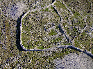
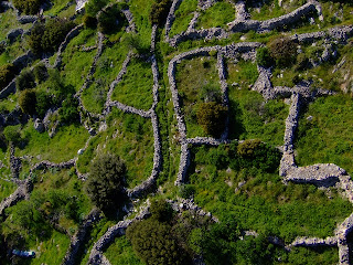
Ancient stone heaps , Χουβέλες στο Αίπος

Ancient stone heaps , Χουβέλες στο Αίπος

Aquaduct over Koufos stream, Το υδραγωγείο στο ρέμα του  Κουφού

Chios landscape ,  Ανοιξιάτικο τοπίο


Δότια Χίου , Dotia Chios

Byzantine tower at Dotia ,Chios . Βυζαντινός πύργος στα Δότια

Anavatos - Chios  Ανάβατος Χίου
 Here is a low-resolution video from the aerial camera.