Εμφάνιση αναρτήσεων με ετικέτα REMOTE CONTROL. Εμφάνιση όλων των αναρτήσεων

Πέμπτη 3 Ιανουαρίου 2013

CENTRALIZED SPLIT UNIT AIRCONDITIONING CONTROL

  Maximum HVAC efficiency is obtained with the use of inverter airconditioning units that have a  CEP  3.5 or more.
  The idea is to control some (3 or more) sets of split type airconditioner units with a central (master)  unit.  This  master unit runs a time schedule by reading the onboard RTC, logs data and slave responces to a micro SD card,  communicates with the slave units via RF24L01+ modules at 2.4GHZ and even takes care of local room temperature by reading a precision centigrade temperature sensor LM35Z and controlling   the local airconditioner unit with an IR led that emulates the original (Hitachi's) infrared remote control. And last , but not least, an input from a power meter (like an Electric Owl CM160 ) monitors electric power consumed by all air conditioner units to prevent power overload.  
  Slave units comunicate with master via  RF24L01+ modules,  read temperature with a LM35's as well , and send infrared commands to the remote airconditioner units. In case of RF link failure they can even take over  local control.
     All units are based on Arduinos's MCU's. Behind the idea of centralised HVAC control is, of course the optimisation of mains power consumption. Below is a photo of a master unit  prototype. On the prototype shield on top of an Arduino duemillenove, you can see the RF24L01+ module, the RTC module (a DS1307) with the backup battery, the infrared led and 2N2222 driver. The temperature sensor LM35Z is behind the RTC module adjacent to the analog pins of the shield. Sd card is an optional add-on . On the paper are my so-far failed attempts to decode the manchester-encoded pulses of the electric Owl's  CM-160 receiver output. On the oscilloscope you can see the infrared pulses that control the shutter of a Pentax X-5 camera which plays the role of the receiving airconditioner unit just to make sure that no interrupt handling inside RF24,RTC,SD,SPI  or WIRE libraries interferes with the time sensitive infrared carrier signal of 38.4KHZ Two buttons are also  provided to send commands like "emergency Power OFF all units" or "set all units to SLEEP 1H  mode".  

Master unit prototype
Code on the master unit takes approximately 26K of flash memory and on the slave a mere 14K.(Atmega328). We can also provide all units with PIR detectors to sense human presence and to inform master to take care accordingly. Every unit can also be connected via USB to a pc for debugging purposes.  

Σάββατο 6 Οκτωβρίου 2012

CAMERA SERVO ADD-ON

Here is a servo adapter for non-infrared remote controlled cameras. Upper servo controls shutter and lower zoom functions. Servo position can be adjusted to fit multiple camera makes. The video shows adapter controlled by the arduino universal remote camera controller which controls the camera array of my previous post.
.

This adapter can be controller by a pc via an rf (xbee) link or arduino's serial usb port , the mini remote control shown here, the hacked helicopter remote control of the previous post, any  PWM R/C remote or by using time lapse and PIR / infrared barrier ports /buttons  on board  arduino pcb

Τρίτη 18 Σεπτεμβρίου 2012

REMOTE CONTROLLED CAMERA ARRAY

I really like remote controlled cameras. Unfortunatelly, affordable ones are very rare these days (like Pentax Optio S1) . An infrared remote control was considered standard accessory during the good old days of  mini-dv and other  tape camcorders but now one has to try hard to find the little red-purple  piece of plastic at the front face of contemporary video equipment.
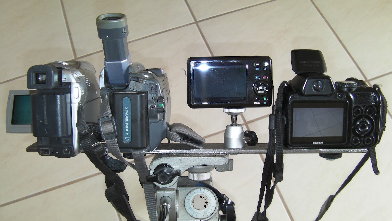
So,I  decided to make an arduino infrared remote controlled camera array . An arduino prototype board with an infrared led and two servos controls at least four different pieces of video equipment and has a few  options useful for nature and wild life photography as well.  A motorized camera rig is on the way.
Oblique view of the  camera array

Rear view of the camera array
Camera array in action


Arduino sends infrared remote codes to the cameras in order to control functions like shutter press/release, zoom in /out, snapshot recording and video recording toggle. Arduino infrared is controlled remotely by either by a  PWM R/C remote control , a serial  digital link (or Xbee) ,  a 433MHZ 4-Channel  button remote control or locally using butons on the arduino board itself. Even two servos can be connected on the board to control shutter and zoom in manual-only cameras. A relay output and an user configurable input can be connected to a PIR detector or an infrared barrier.
A "hacked" 433MHZ radio link -we just get TTL Rx/Tx signals and 5V to feed  Arduino

Arduino infrared prototype feeded by a  7.4V  LiPo (5400mah!!) , a 3A/ 5V swiching regulator, and a hacked 433Mhz serial link . Bottom center is the Infrared led and one of the two optional servos for shutter and zoom functions.  

The not-so-innocent cheap helicopter model remote control and hacked  433Mhz serial receiver. Everything inside original remote  was discarded and a 433Mhz serial link (the same as the receiver) was added  together with an arduino mini at 16 Mhz, another  two axis left joystick and two extra buttons below it.  Power comes from  4 NimH batteries and a 5V/3A switching regulator,  Line-of-view range is about 300 meters.  

Arduino infrared prototype is controlled by an -also hacked - 4-channel 433 Mhz garage door  receiver. The minimalistic remote shown on the right has a line-of-view range of 300 meters ! It can control shutter , Video recording and Zoom functions of every camera in  the array.   

 2 channels of a common  PWM R/C receiver are connected to the arduino prototype. We can control  shutter , Video recording and Zoom functions of every camera in  the array also,  using flap  (CH6) switch for shutter and Video record toggle, and  throttle (or elevator) joystick (CH3/CH1) for Zooming functions.     

Another useful option is the built-in intervalometer   which takes time-lapse videos like this one :

You can see a FHD of the above video if you click on the following  link :
or this one :


Δευτέρα 26 Σεπτεμβρίου 2011

MEADE ETX-70AT TELESCOPE REMOTE PC AND ARDUINO CONTROL

These fine nights of September when Orion rises early the morning above the horizon, and Jupiter dominates the sky, its a pleasure to use the small ETX-70 telescope guided by its Autostar 494 controller. That telescope costed a mere 200 Euros at Lidl and in my opinion it isn't just a fine little telescope for the beginer, but it's also  perfect for land surveing. When Lidl sold its Bresser microscope (another 60 Euros welll spend), it supplied it with a USB camera that fits not only to the microscope , but via an (supplied) adapter to the 1.25'  eyepiece holder of the ETX-70. Even though the USB video adapter has a resolution of just  640 x 480 pixel , it is very good for land surveying as  shown on the following  video. At this case the distance to the subject (the Mi-8 Helicopter) was about 2.5 kilometers, temperature was about 27 deg. C, a sea area existed between the scope and the target and atmospheric conditions far from perfect. Barlows 3x lens was also used that deteriorated the resolution but I wanted to push it to its limits.


From the point of view of an electronics engineer the most interesting feature of the ETX-90  , is the precise guiding mechanism which can be controled by the computer's serial port. All you need is the optional 506 cable set from Meade which is actually an RS232 to I2C adapter that connects to the AUX port of the microscope. A lot of info is written about Meade's serial protocol but the best way to learn about it (exactly as I did) is to tap the serial cable and spy on the data when controlling the telescope with a proper software such as Drsoft 's Meade control panel , Carte des Ciels or Stellarium. A much more elegant solution to taping the cable is to duplicate the controling serial port using a serial to ip server, and open a teminal (like TeraTerm) at 9600N81 to view and log the traffic.After all my finds were :

#:Mn#  Slew north (up)
#:Ms#  Slew south (down)
#:Me#  Slew east  (left)
#:Mw#  Slew west  (right)

#:Mw##:Mn#  Slew right up    (NW)
#:Mw##:Ms#  Slew right down  (SW)
#:Me##:Mn#   Slew left  up    (NE)
#:Me##:Ms#   Slew left down   (SE)

#:Qn##:Qs##:Qe##:Qw# Stop movement after above commands
#:Q# Stop movement for all motors

#:Sw2#   Slew speed slow
#:Sw3#   Slew speed medium
#:Sw4#   Slew speed fast

FOCUS  CONTROL - there isn't any focuser on the scope - we will talk about it later.
#:F+#    Focus +
#:F-#   Focus -
#:FQ#   Focus Stop
#:FF#   Fast Focus
#:FS#   Slow Focus
 
After reading the excellent info on http://www.weasner.com   I learn that : " when typing a single control-F on the terminal  the Autostar should echo an "A" or "P" depending upon whether it's
 set up as Alt/Az or Polar mount status and when typing #:GVF#  it should respond with its identification string, including the word Autostar and a time and date (when that firmware version
 was built at Meade) ".
Indeed  :
 Ctrl -F    ---> A
#:GVF#   ---> #Autostar|A|12Ea #